Pelican's rusty old Volvo
|
|
|
Pelican's rusty old Volvo |
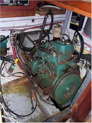
As we described in our February 2002 log, we decided to go ahead and replace our 25-year-old 13 hp Volvo MD7A diesel with a newer, more powerful diesel this winter.
After much research and pricing comparisons we decided we would go with a Yanmar 3GM30 if it would fit in our engine space. Amazingly, this engine at 26hp was 100 pounds lighter than the old 13hp Volvo. We also liked the Yanmar name from experience with the 16 year old Yanmar 3QM30 on Jenny P which still ran like a top. Now it was time to remove the old engine and take some measurements to see if we could make the Yanmar fit.
The week after Christmas 2001 we began to disconnect wires and disassemble portions of the old Volvo to ease removal. Finally, with the help of Sara’s dad’s chain hoist, we were able to lift out the old engine and clean up the engine compartment. After taking some measurements, we were disappointed to find that the Yanmar 3GM30’s engine mounts were too separated in a fore-aft direction. Even the Yanmar 2GM20 had not enough clearance for the mounts to fasten to our existing engine stringers without punching through the hull! Back to the Internet for research on other comparable fresh water cooled ~26hp marine Diesel engines.
 |
|
Glassing in the new engine mounts |
We found that the Universal M-25XPB was comparable to the Yanmar 3GM30 except that it had alternate engine mounts which allowed the mounting feet to be considerably more forward and closer together than either of the Yanmar models. The M-25XPB was also 100 pounds lighter than the Volvo, fresh water cooled, 26hp and came with a very nice engine control panel which includes coolant temp, oil pressure, voltage, tachometer, hour counter and a nice key switch. The Yanmar panel has only a tachometer and the rest of the indicators are idiot lights.
The next step was to build a plywood jig to the same measurements of the new engine. Fortunately the website above had a nice Adobe PDF format dimensional drawing of the engine which allowed us to determine exactly where each extremity of the engine would be inside our compartment. From this drawing we were also able to determine exactly where the centerline of the engine output flange would be on the transmission. This last item is extremely important when installing an engine. Don Casey's articles on repowering from Good Old Boat magazine were very helpful in explaining the whole engine alignment process.
Next we created two slots using L brackets on the forward and aft ends of our plywood jig to represent the centerline of the engine output. With no engine in the engine compartment we were easily able to run a string from the propeller aperture through our shaft log and into the engine space to simulate the exact center of the prop shaft. With the string taught, we slid the jig underneath so that the L brackets grabbed the string. With the jig in place, we found that our engine bed would need to be raised by approximately 2 inches on the aft end and a little over 3 inches on the forward end.
 |
|
New engine mounts and |
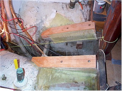
We were unable to find a 3 inch thick chunk of oak so settled with a 2 inch piece laminated together with West Systems epoxy. On New Years Day we were able to find a woodshop owner who answered his telephone - though his business was closed he was only there finishing the books! Lucky we were!
That afternoon we epoxied and lag bolted the two angled oak stringer shims to the existing stringers. The following day we glassed them in place with 4 sheets of heavy roven woving – one on each side of each stringer shim. A few days later after all the epoxy had cured; we lightly sanded and painted the entire engine space with Rustoleum enamel white (cheaper but the same thing as marine bilge paint). At this point we were ready to pick up the new engine at Stuart’s Marine in Ballard and lower it into the compartment.
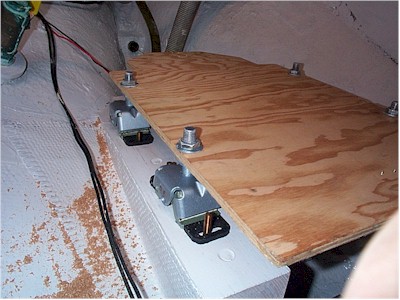
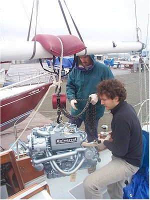
With help from a couple of friends and the trusty chain hoist, we lifted our new engine from the ground and into the engine compartment using the boom as a crane. This process was extremely nerve wracking to say the least! Immediately before lifting the new engine into place we had removed the four engine mounting feet which came installed on the new engine. After removing these, we installed them on our plywood jig in exactly the same position they would be on the engine itself. This allowed us to precisely mark the holes for the hanger bolts which hold the engine in place.
Once the hanger bolts were installed, we removed the feet from the plywood jig and bolted them down to the stingers. Now we had four large bolts that fasten the feet to the engine itself standing vertically ready to accept the engine when it was lowered into the compartment.
 |
|
Installing engine mounts using template |
Amazingly, the engine fell into place without a hitch! When looking through the shaft log from the propeller aperture, the center line of the engine output flange could be seen almost perfectly in the center. All of our tedious measuring paid off! Ahead of us were all of the fuel, water, electrical, exhaust and shaft connections.
After a few more weekends spent measuring, cutting and connecting hose and cable, we were ready to fire up the engine for the first time. Of course we were on the hard, so using a garden hose to a bucket in our galley sink, we dropped the engine sea water intake hose into the bucket and turned on the faucet – this would allow the sea water pump to draw just the right amount of water as opposed to forcing water into it directly from the garden hose. To our delight the engine fired up immediately and what a sweet sound it was! We inspected everything for leaks and tightened down accordingly then moved on to install the prop shaft, coupler, PSS seal and R&D flex-coupling.
 |
|
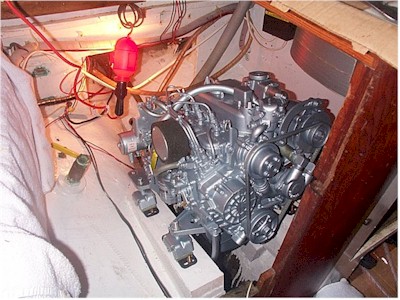
Hoisting the new Universal |
Unfortunately we had already had a shaft and coupler made for the Volvo which was too short for the new engine and doubted we’d get much credit for their return on a new, longer shaft. The Prop Shop gave us 80% credit on our return and a good price for the old Left Hand 2-blade prop towards a Right Hand 3-blade version with a steeper pitch which was computer matched to the new engine and our hull. Once all the parts were exchanged, we pieced everything together (don’t forget the PSS seal!) then slowly whacked the new shaft into the new split coupler with a 2x4 from the outside of the boat. Before installing the new R&D flexible coupling between the engine output flange and the shaft coupling, we aligned the two rigid couplings within .003 of an inch using the horizontal engine feet slide adjustments and vertical engine feet bolts. Once this was accomplished using a feeler gauge, we slid the flex coupling into place and tightened all of the coupling bolts. At this point, with the exception of bottom paint and a few on-going blister repairs, we were ALMOST ready to launch. The last item being the engine control cables.
The Volvo had used a single lever Morse control mounted to the side of the cockpit. We decided to purchase instead a dual lever Edson control module for our Edson steering pedestal. After receiving the parts via mail order, we attempted to install them and found they were the wrong size. Additionally, we discovered that our Edson pedestal (which may not have been Edson at all) was badly corroded on the inside with stainless bolts frozen to the aluminum around the compass mount. It was at this point we decided to rip out the entire pedestal steering system and go back to the original Alberg 35 tiller arrangement. We returned the dual lever Edson controls and kept the single lever Morse control on the cockpit side.
 |
|
She fits!!!!! |
We purchased new Morse cables of the right length (2 feet longer than the Volvo for both the transmission and throttle controls) and installed them to the old single lever control without issue. The engine installation manual warns that the transmission control lever must travel a minimum of 35cm in each directly from neutral or partial gear engagement can occur which will prematurely wear out clutch discs. A metric ruler proved we had more than enough travel.
Now all that was left was installing a stop cable and mounting the control panel in the cockpit. Before sealing the panel, we would have to adjust the Tachometer using an optical tach gauge. We also discovered that our companion way step would need a very slight adjustment to clear a water temperature sender on top of the engine, so a little cabinetry work was also in order! But having successfully installed a new diesel in our old Alberg 35, anything else will be a snap (knock on wood of course)....
We highly recommend people to do this type of job yourself, not only so you know your boat like the back of your hand (which we do now after hours and hours of hanging in the bilge), but to save money. Unless you have lots then never mind.
The engine itself cost $6000 (about $1000 less than a comparable Yanmar, so this was another thing we liked about the Universal). A quick look in our MS Money program shows we spent approximately $2000 in January on sailboat supplies and maintenance, and we are assuming this was largely engine expenses, plus new prop, (both) shafts, PSS seal, coupling etc. The little things really add up: new wires and cables, hoses, exhaust fittings, new seawater strainer, bolts, epoxy.
At $8000 total, this is what we expected to spend. We did sell the old Volvo for $500 which was a definite plus. We think it was $7500 well spent as it will allow us to probably not have to deal with the engine at all for many years.
Back to the Projects & Ideas Index